.svg)
High System Efficiency
Efficient electrical distribution is essential for reducing operating costs, improving equipment life expectancy, and maintaining regulatory compliance. Two commonly overlooked issues, voltage drop and low power factor, can significantly impact your “bottom line” and degrade the overall system performance if not proactively addressed.
What is Voltage Drop?
Voltage drop is the reduction in voltage as electrical current flows through conductors with finite impedance. It is governed by Ohm’s Law:
Vdrop = I x Z
Where Vdrop is the voltage drop, I is the current and Z is the impedance
A high current draw, long conductor lengths, or undersized cables increase the drop. Excessive voltage drop reduces equipment performance and increases heat losses. Industry guidelines emphasize maintaining voltage within ±5% of nominal to ensure equipment operates within design parameters (IEEE Std. 141 [Red Book]). They also recommend a maximum of 3% voltage drop on a feeder or branch circuit, and 5% total from service entrance to load for “reasonable system efficiency.” (NFPA)
Impacts of Voltage Drop
- Reduced Equipment Performance: Motors will draw higher current at lower voltage to maintain torque, leading to overheating and insulation wear.
- Higher Operating Losses: Increased current amplifies I²R losses in distribution conductors, increasing energy costs.
- Nuisance Tripping: Undervoltage conditions can lead to breaker trips, especially during motor starts or peak demand periods.
- Reduced Equipment Life: Continuous undervoltage stresses transformers, UPS systems, VFDs, and motor windings.
Low Power Factor and its Negative Impact
Understanding Power Factor
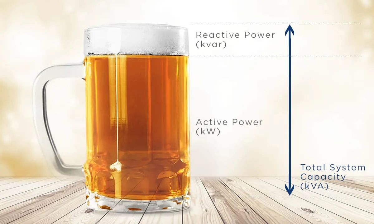
Power factor (PF) is the ratio of real power (kW) to apparent power (kVA):
PF = kW / kVA = cos𝜙
A low PF (<0.9) indicates a system drawing more current than necessary for the useful work performed.
Impacts of Low Power Factor
- Increased Current and Losses: A lower PF forces higher current for the same real power, increasing I²R losses, voltage drop, and energy costs.
- Utility Penalties and Demand Charges: Most utilities impose penalties when PF falls below a specified limit (typically 0.85–0.95). Poor PF increases kVA demand, raising monthly bills.
- Overstressed Electrical Components: Transformers, switchgear, conductors, and generators must be sized for higher kVA, not just kW.
- Reduced Voltage Stability: High reactive power flow increases system reactance-related voltage drops, leading to instability during peak loading.
Combined Effect: Voltage Drop vs. Power Factor
Low power factor increases current. Increased current increases voltage drop. For induction motors, reduced voltage can cause higher current draw, magnifying losses. While this interaction can resemble a feedback loop, the system reaches a new operating point rather than entering an unstable loop. Low power factor and undervoltage commonly occur together in motor-dominated installations, but one is not necessarily the root cause of the other.
How to reduce Voltage Drop and Increase Power Factor in your electrical system?
1. Check with your utility if you are being charged penalties for low power factor
2. Perform a comprehensive Power Study of your electrical system
A comprehensive power study typically requires:
- Creating a Digital Twin of your electrical system on a software like ETAP
- Performing Load Flow, Short Circuit and Harmonic studies
- Analyzing mitigation strategies to reduce voltage drop and improve PF in your electrical system
- Designing specific engineering solutions to improve PF and reduce voltage drop
3. Implement Mitigation Strategies and Engineered Solutions
A comprehensive power study can provide different mitigation solutions based on the specific characteristics of your operation balancing cost, operational requirements and ROI. These can include:
- Conductor Upsizing: Larger conductors reduce R and X.
- Shortening Feeder Lengths: Optimize distribution topology.
- Autotransformers or Voltage Regulators: Maintain stable voltage for long feeders.
- Load Balancing: Reduce current on heavily loaded phases.
- Capacitor Banks (Fixed or Automatic): Most cost-effective solution for inductive loads.
- Synchronous Condensers: For large industrial systems requiring dynamic PF correction.
- Active Power Factor Correction (APFC): Effective for non-linear loads (VFDs, computers, LED drivers).
- Motor Management: Oversized or lightly loaded motors should be right-sized or VFD-controlled.
Our Case Study: Low Power Factor Analysis for a Mine Expansion project
The following is a case study on one of Potential Engineering’s projects.
Project Overview
As part of an expansion, a copper mine required a power system study to ensure that the electrical system in the expansion area could support the new loads. The site’s electrical system was supplied at 138 kV with an internal distribution system at 13.8 kV. The main loads operated at 4.16 kV and 0.48 kV.
Key Objectives
- Ensure the reliability and efficiency of the electrical system with the added loads
- Design any required engineering solutions to ensure a reliable, efficient and safe electrical operation
Methodology
- Data collection, field measurements and system modelling
- Load Flow, Short Circuit and Harmonic Analysis
- Design of engineering solutions including budgetary costs for ROI calculation
- Follow up field measurements to ensure effectiveness of implemented solutions
Key Findings
- High Voltage Drop in three locations: With the additional loads, three 4.16 kV Switchgears exceeded 6% to 7% voltage drop under normal conditions and 14% to 16% drop during motor start up.
- High power losses during normal operating conditions: With the additional loads, the overall power losses in the electrical system went up to 696 kW
Solutions and Recommendations
- New Transformer Taps: Implement new transformer tap settings on three 13.8/4.16 kV and two 4.16/0.48 kV transformers to reduce voltage drop.
- Capacitor Banks: Install three individual capacitor banks at 13.8 kV to improve power factor and voltage stability.
The client implemented all the recommendations and obtained a 29% reduction in power losses.
Typical Energy Cost Savings for a similar system in Alberta:
Saved Power: 696 kW * 0.29 = 201.84 kW
Annual Energy Saved: 201.84 kW * 8,760 Hrs/year = 1,768,118 kWh/year
Annual Cost Savings: 1,768,118 kWh/year * CAD$ 0.12/kWh = CAD$ 212,174
Final Thoughts
Voltage drop and low PF are silent killers of efficiency and lead to increased operating costs and potential premature equipment failure. Through proper power system design, corrective equipment, and targeted engineering analysis, these issues can be both diagnosed and cost-effectively mitigated.
Implementing voltage drop reduction and power-factor correction provides tangible financial and operational benefits:
- Lower energy bills and elimination of power-factor penalties
- Improved system stability and reduced downtime
- Extended equipment lifespan
- Reduced conductor and transformer losses
- Increased available capacity in existing infrastructure
- Compliance with NEC, IEEE, and utility requirements
For support with an assessment of your facility’s distribution system or a detailed power-quality study, please contact info@potentialengineering.ca